This topic will take you through setting Alarms.
Levels
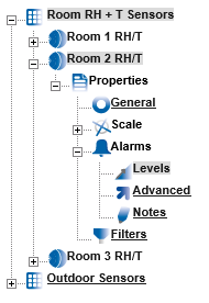
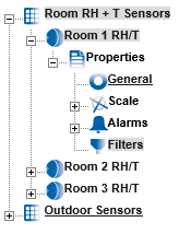
To access Alarm Settings click on the + symbol next to Alarms (in Edit Mode). This will expand the branch again, see below.
|
To access Levels click on Levels. See below. |
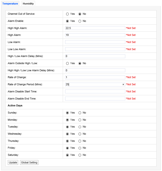
The Sensor in this example is a two-channel temperature and humidity device. You will see two tabs at the top one marked Temperature and highlighted, the other marked Humidity. The highlighted tab is the active tab. The tab names will change depending on sensor type, the number of tabs will change depending on the number of channels.
Channel Out of Service
This feature allows a single channel on a dual channel device to be taken out of service. This is useful as it may not be desirable to take the whole device out of service for example if a dual channel temperature transmitter was being used to measure the temperatures in a fridge freezer and the freezer had failed or was not in use the channel associated with the freezer could be taken out of service. This would allow alarms from the fridge to come through the system but there would be no alarms from the unused freezer.
To take a channel out of service select the appropriate tab and select the No option button to take that channel out of service. When the channel is required again select the Yes option button.
Alarm Enable
If a Sensor is temporally out of service, or if the alarms are temporally not required rather than set all the alarm settings to zero the alarms can be disabled. To disable the alarms select the No option button. When the alarms are required again select the Yes option button.
High/High High Alarm
The High High Alarm is the highest level alarm that can be set on the system. This alarm should be set at a level that warns the user of potential damage. (High would represent the highest point of the desirable working range.) To set the High High Alarm type a value in the text box next to High High. The level can be set to one decimal place.
Low/Low Low Alarm
The Low Low Alarm is the lowest level alarm that can be set on the system. This alarm should be set at a level that warns the user of potential damage. (Low would represent the lowest point of the desirable working range.) To set the Low Low Alarm type a value in the text box next to Low Low Alarm. The level can be set to one decimal place.
High/Low Alarm Delay (Mins)
The high/low alarms can be delayed, which is very useful to prevent false alarms. In many buildings rooms are air conditioned to keep the environmental conditions constant. The conditions in any room change when doors are opened but soon recover when the door is closed again.
If alarms are set these could be activated every time a door is opened which would generate many alarms on the system. There is a danger with alarms that a syndrome called alarm fatigue develops where alarms are generated so frequently that they become an annoyance and are consequently ignored.
To avoid this a delay in minutes can be set for the alarms. For example when a door is opened the temperature drops but has recovered back to normal 10 minutes after the door is closed, without an Alarm Delay an alarm would be generated every time the door is opened. With an Alarm Delay of 15 minutes there would be no alarm generated however if the door was left open there would be an alarm generated after 15 minutes. To enter a High/Low Alarm Delay enter the time in minutes in the text box next to High/Low Alarm Delay.
Alarm Outside Range
To activate High/Low Alarms click the Yes option button. To disable High/Low Alarms click the No option button.
High High/Low Low Alarm Delay (Mins)
This feature allows a delay to be activated on the High High and Low Low alarms. It is generally accepted that no delay is enabled on the High High and Low Low alarms as these are normally the fail safe alarm levels. If delays are used here it may be that a very small delay is used to avoid a single reading out of spec generating alarms. To put a delay on the High High and Low Low alarms type a value in the text box next to High High/Low Low Alarm Delay (Mins), and should be entered in minutes.
Rate of Change
This feature activates rate of change alarms, depending on the application, a high and low level alarm may not work. A Rate of Change alarm is a mechanism that monitors how fast a parameter is changing and generates an alarm based on the selected criteria. For example, and alarm could be generated if temperature changes by more than 10°C per minute.
To set the Rate of Change enter a value in the dialog box next to Rate of Change. For example, a value of 10 would mean 10°C per minute if temperature units are set to °C. (See Global Units for how to set units.)
Rate of Change Period (Mins)
This feature is used together with the Rate of Change value above. Rate of Change Period is the time period associated with the Rate of Change value. This would be entered in minutes, so combined with Rate of Change would work like this - if the temperature changed by more than 10°C in 5 minutes an alarm would be generated. To set the Rate of Change Period enter a value in the field next to Rate of Change Period (Mins).
Alarm Disable Start Time
This feature allows alarms to be disabled during certain time periods. For example if a room is used during the day to work on sensitive items, alarms would be required during the day, but not required during the night. To set the Alarm Disable Start Time enter the time in the field next to Alarm Disable Start Time and should be entered like this: 18:00:00 in hours, (24 hour clock format) minutes and seconds. All alarms will be disabled after 18:00.
Alarm Disable End Time
This feature works together with Alarm Disable Start Time and sets the reactivation time for alarms. To set the Alarm Disable End Time enter the time in the dialog box next to Alarm Disable End Time and should be entered like this: 08:00 in hours, (24 hour clock format) minutes and seconds. All alarms for this device will be active again after 08:00:00.
Active Days
This feature allows alarms to be turned off on certain days. For example where sensitive goods are worked on during the week and put away each evening and at the weekend alarms would not be required at these times. The weekday alarms are handled by Alarm Disable Start and Stop Times. The weekends can be handled by disabling the alarms on Saturday and Sunday. To disable alarms on certain days select the No option button. In this example we want to disable the alarms on Saturday and Sunday. To do this select the No option button next to Saturday and Sunday. To make those days active again select the Yes option button.
Once you are happy with your selections click Update. The alarm settings will be saved. The above can be repeated for the second tab if applicable. After selecting Update and the settings are saved the settings page returns with a message “Record updated successfully” see below.

The example dialog box below shows a correctly completed temperature alarm settings page. The actual values will change depending on the measuring parameters, every application will be different. The example shows a high level alarm of 25.5°C, a low level alarm of 5°C with a delay of 5 minutes. The high range is set to 20°C and the low range to 5°C with a delay of 5 minutes.
There is a rate of change alarm active which will alarm if the temperature changes by more than 10°C in 5 minutes. All alarms are disabled between the hours of 8am and 6pm and there will be no alarms at any time on Saturdays or Sundays.
| Caution: | Alarm fatigue can be a major problem on automated monitoring systems especially when the alarms can drive emails or SMS alerts to call out service personnel. |
| There are many circumstances where the conditions of a room or space are not actively controlled and are driven by outside forces such as what’s happening next door or the weather outside. In these cases there is little point setting alarms that would relate to ideal conditions, especially if those conditions couldn’t be met on a daily basis. In these cases it is better to have no alarms set. |
| The danger of receiving many alarms that do not have an action where something can be done to prevent the re-occurrence of that alarm is the main cause of alarm fatigue. |
| If on the same system there was a critical space with high value objects that was controlled by an HVAC (Heating Ventilation and Air Conditioning) system, and on system failure an alarm was generated there is a great danger that this alarm could be ignored. |
We are not suggesting that alarms are never set in these conditions just that thought and consideration are given during the alarm setting process.
Digital Alarms are Alarms generated by digital channels that record data from devices such as ‘door open’ sensors. Digital channels can only have two states, which are analogous to open or closed. The example dialog box below shows the alarm Levels settings view for a Digital channel:
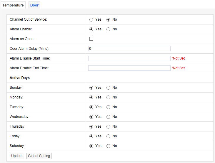
For a door open/close sensor, Alarm on Open would give an alarm if someone opened the door.
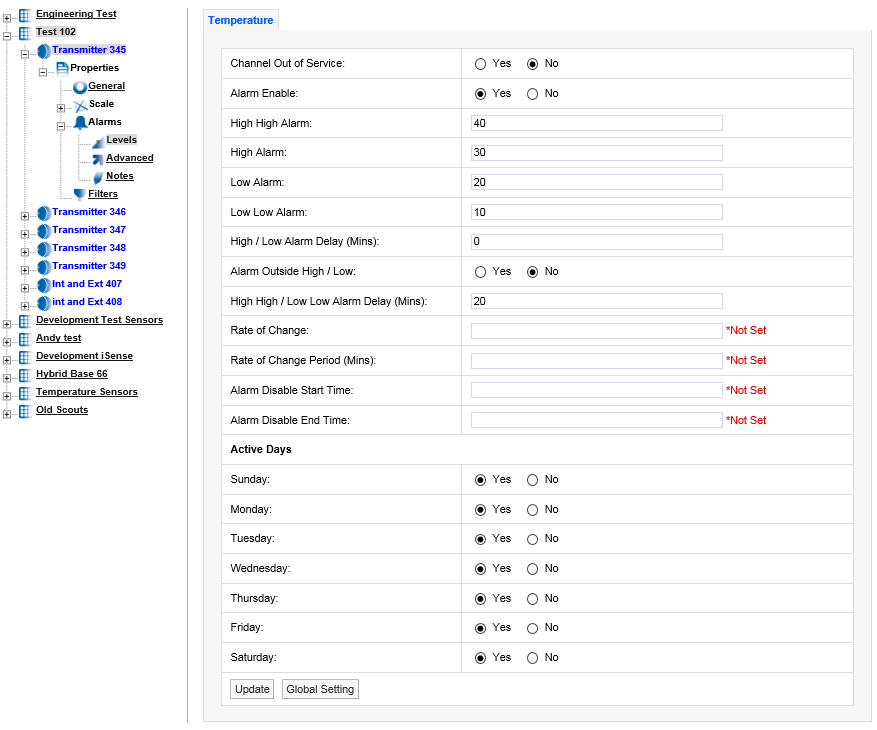
If there are many Sensors/Transmitters on the same system doing the same function in different spaces it can be tedious and error-prone to go through all the Sensors/Transmitters on the system. There is a facility to change the Alarm settings globally on a number of sensors.
To make global changes stay on the alarm settings tab that you want to use to update other Sensors/Transmitters with and select Global Setting at the bottom of the tab. A new window will appear, see below.
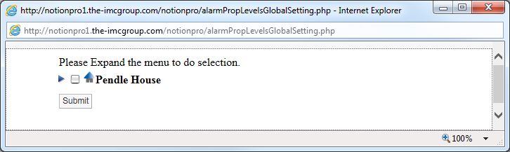
To expand the tree, select the blue arrow to the left of the Site name, see below.
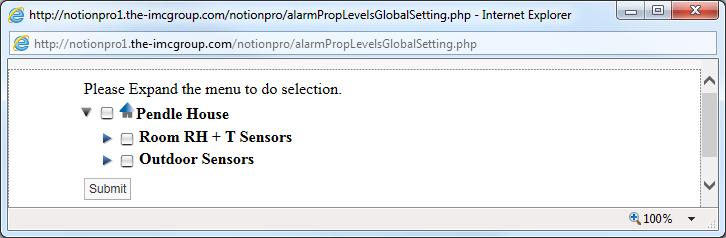
To see the Sensors/Transmitters in a Zone click the blue arrow to the left of the Zone name, see below.
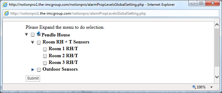
To select the Sensors/Transmitters to update the alarm settings either click in the tick box next to the Zone name which will select all the sensors in that Zone or individually select each sensor in turn by clicking in the tick box next to the Sensor name, see below.
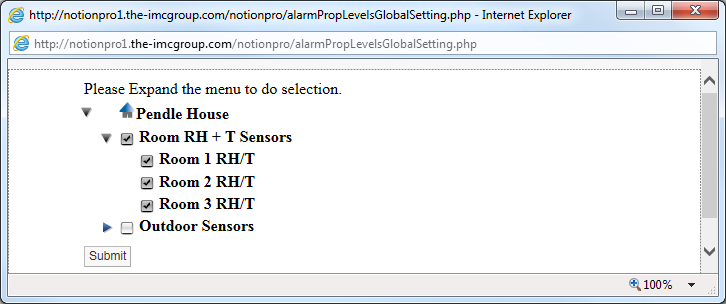
Once you are happy with your Sensor selections select Submit. The selected Sensors will now be updated with the alarm settings from the selected Sensor. This can be checked by going into the alarm properties of another Sensor.
Advanced
To edit the Advanced settings select Advanced. A new window called Alarm Advance will appear, see below.
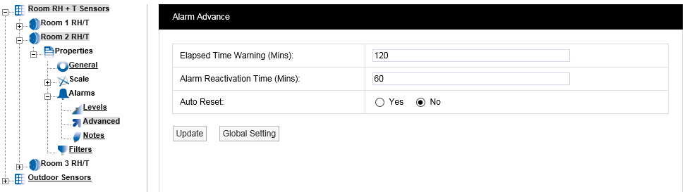
The elapsed time warning is used to alarm when a signal is not received from a Sensor within the predetermined time. In the default settings the Elapsed Time Warning is set to 120 minutes. This can be changed to any time up to 999 minutes. It is not recommended to set the Elapsed Time Warnings to very long periods. If there are lots of Elapsed Time Warnings being generated this may be an indication of a more serious problem such as poor radio coverage.
The main purpose of the Elapsed Time Warning is to alert you that a problem has occurred such as a Sensor has failed, been moved out of radio range or has inadvertently had the battery removed.
There are occasions where all the sensors in a Zone or Zones that are served by a wireless receiving device go into Elapsed Time Warning at the same time. This would be caused by either a failure in the wireless receiving device or a network problem causing the wireless receiving device to stop communication with the database. If such problems are seen then these need to be investigated.
To set the Elapsed Time Warning period enter the required time in minutes into the field next to Elapsed Time Warning.
Alarm Reactivation Time (Mins)
The Alarm Reactivation Time is the default setting for the time between acknowledging an alarm and when the system checks to see if the alarm condition has returned to normal.
If the alarm condition has returned to normal the alarm status will change from amber (acknowledged) to green (OK), if after the Alarm Reactivation Time the alarm condition still exists the alarm status will return to red (unacknowledged) and create a new alarm on the system.
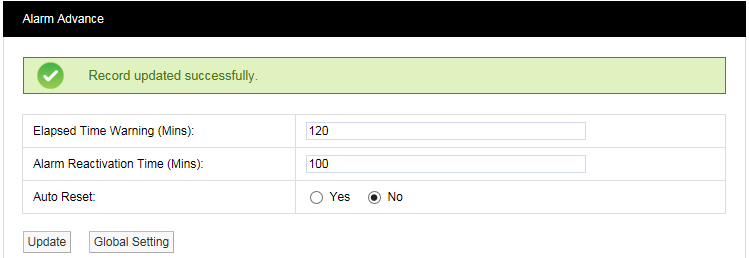
The default setting is 60 minutes. To change this enter a new value in minutes in the field next to Alarm Reactivation Time.
Auto Reset
Auto Reset is used to reset an alarm status to green when an alarm condition returns to normal. The default is No which means that all alarms have to be acknowledged. The disadvantage is that a Sensor could go in and out of alarm all night but when the User checks in the morning the status shows green, so without looking at the graphs or alarm logs they would be unaware of a problem.
To change the setting select one of the Yes or No option buttons as required.
When happy with the settings click Update. The setting will be saved, see below.
To edit the Notes settings select Notes. A new window called Alarm Notes appears, see below.
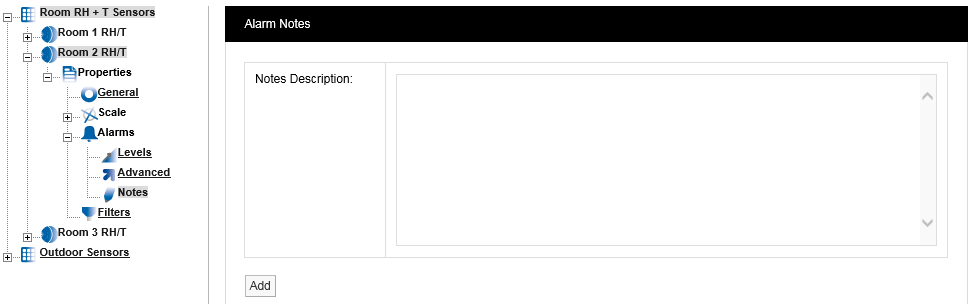
This feature allows you to enter notes for an Alarm. This is especially useful for inexperienced operators. The system can be set up so that low-level users can monitor the system but can’t make changes. The Alarm Notes will give an inexperienced user specific instruction on what to do when an Alarm occurs.
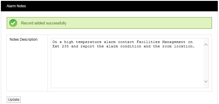
For example in the middle of the night the temperature increases in a room or space containing high value objects, an Alarm is generated and a night shift operative or security guard views the Alarm. The Alarm message might say “On a high temperature alarm contact Facilities Management on Ext 235 and report the alarm condition and the room location”. This feature means that someone not familiar with an area or its contents can still effectively and efficiently deal with an alarm condition.
To activate this feature type your instruction into the dialog box and when happy select Add. This will add the message to this Sensor. This can be set individually for every Sensor on the system. Once the changes have been added and are OK you will see the following window, see below.
Filters
This feature lets you set filter limits for the Sensor. These should only be used in exceptional circumstances. For example if a Sensor is located in or near an electrical switch panel which can be very noisy electrically this can occasionally cause interference on the radio link, which would be seen on the graph as a large spike in the data.
The filters are designed to remove such interference. If the Sensor is reading temperature and the expected range for this application is -10°C to +50°C a filter could be set at say -40°C for the Min Value and +80°C for the Max Value. Any readings seen above or below these readings would be rejected.
To edit the Filter settings select Filters. The Temperature tab (for temperature in this case) will appear, see below.
|
|
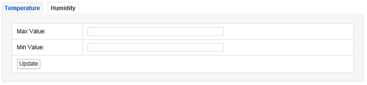
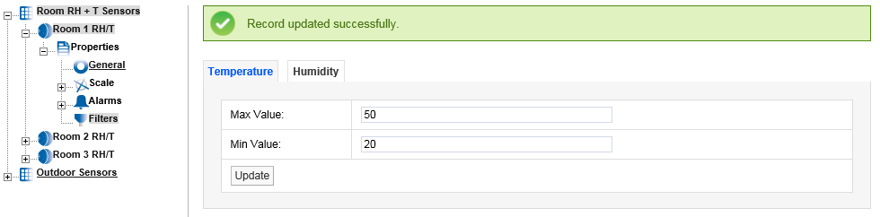
To activate this feature enter the required Min and Max values in the appropriate fields. The values should be whole numbers in the range 50 for the Max Value and -40 for the Min Value. Select Update when finished. (A warning message is given if you click on another tab before you’ve selected Update for a change you made on the current tab.) Once the data is accepted you will see the following screen, see below.
For dual channel Sensors, repeat the above process for the other channel.
Note: Setting filters will cause data to be rejected above and below the filter limits. Check that any filter limits set are above and below the expected ranges.