A typical Notion Pro installation would consist of one or more Network Receivers (sometimes referred to as a Base Station) and a number of sensors (transmitters). For the transmitters, the procedure below (starting at Step 10) would need to be followed for each transmitter that you are using.
The procedure below is for installing the Network Receiver. The procedures for installing the Notion Pro family of Base Units (i.e. the Network Receiver, the Echo Module, the SMS Module and the ARB Module) are very similar.
As far as possible, the Receiver and Transmitter units should be placed where they will not be subject to electromagnetic interference and where they will not be shielded by walls, doors, furniture, appliances etc. See Equipment Positioning for more details.
The FCC Declaration of Conformity should be noted by USA customers.
The ISED Declarations of Conformity should be noted by Canadian customers.
Install Step |
Notes |
|---|---|
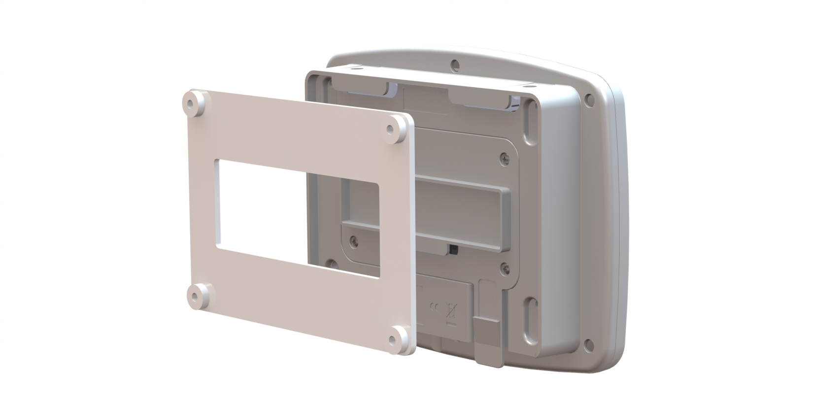
1.Using the mounting bracket as a drilling template, drill holes for the receiver wall mounting bracket into the wall at an appropriate location. 2.Using the spacers provided to give clearance, screw the mounting bracket to the wall. |
When mounting the Receiver, you should bear in mind that you will need to run cables from the Receiver to the mains power supply and to your network socket.
|
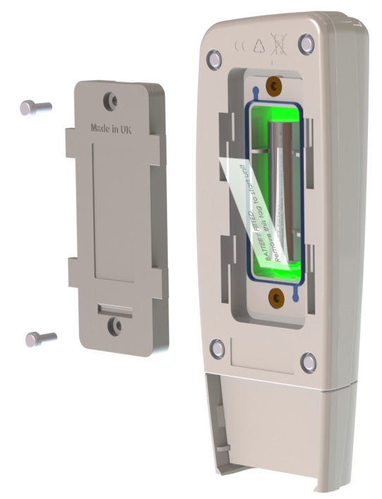
3.Using a Phillips screwdriver, remove and retain the screws from the battery cover plate at the rear of the Receiver. |
|
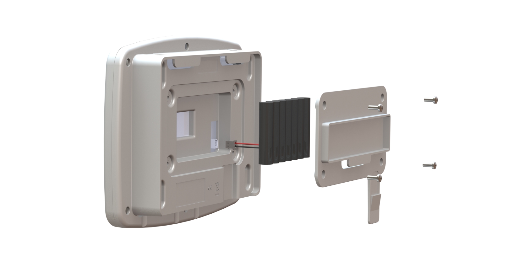
4.Note: If installing an SMS Module, the SIM card must be installed prior to battery installation, see Installation. Insert the 8.4V backup battery into the recess at the rear of the Receiver, taking care to insert the connector attached to the battery into the matching connector within the Receiver.
|
|
5.Screw the battery cover plate to the rear of the Receiver. |
|
6.Attach the Receiver to the mounting bracket. |
|
7.Using the supplied Ethernet cable, connect the Receiver to your Network connection if you have one. |
|
8.Using the supplied cable, connect the Receiver to the mains power supply. |
|
9.If you are NOT using the door monitoring and alarm function option with this transmitter, go to step 11 below. Secure a matching pair of door monitoring and alarm function sensor pads to the door and door frame of your refrigerated/frozen storage unit. |
If you intend to the lay the transmitter loosely in the storage unit, ensure that you position the door frame sensor pad such that the cable running from the pad goes into the storage unit. If you intend to wall-mount the transmitter, ensure that you position the door frame sensor pad such that the cable running from the pad runs outside of the storage unit. Ensure that the pads meet perfectly when the door is closed. |
10.Pull away the contact tag on the transmitter to ensure the battery contacts and the transmitter contacts meet. |
A green light will flash briefly.
The transmitters are powered by 1 x 1.5V Lithium AA cells. Standard AA cells can be used, but are not recommended. (1.5V Lithium AA batteries supplied with transmitter will work over range -30°C to +50°C. 1.5V AA alkaline can be used but will have reduced life and a reduced operating temperature range 0°C to +40°C.) See also Battery. |
11.If you do NOT intend to wall-mount your transmitter, go to step 20 below. |
|
12.Drill holes for the transmitter wall mounting bracket into the wall at an appropriate location. |
When mounting the transmitter bracket, you should bear in mind that, if you are using the door monitoring and alarm function and/or external sensor options, you will need to run cables from the transmitter to your storage unit door frame sensor pad and/or external sensor. |
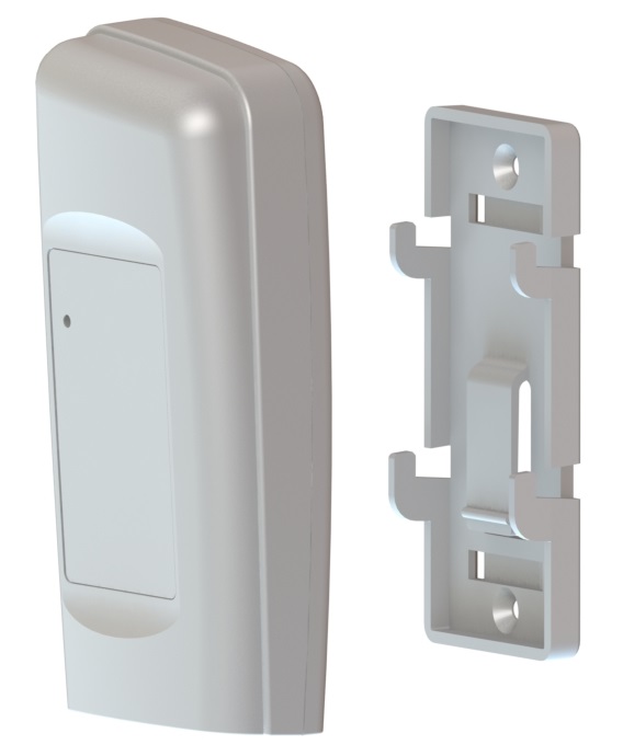
13.Screw the mounting bracket to the wall. |
As an alternative, the transmitter bracket could be attached to a suitable post using cable ties. Slots are provided in the bracket for this purpose. |
14.Slot the transmitter onto the wall bracket. |
|
15.If you are using the door monitoring and alarm function option with this transmitter, route the storage unit door frame sensor pad cable up to the transmitter. |
|
16.If you are NOT using the external sensor option, go to step 20. |
|
17.Place the external temperature probe and associated cable at a suitable position in your storage unit. |
|
18.Route the temperature probe cable over the door frame and up to the transmitter. Insert the cable into the transmitter. |
|
19.Repeat steps 10-19 above for each transmitter that you are using. |
|
20.Plug in the Receiver power supply to the mains supply and switch on at the mains socket. |
The green power LED comes on. |
21.Go into Notion Pro to add transmitters to Zones and set them up for use. |
See Setting Up the Sensor Model for details. |