Multi-Purpose Analogue Sensor-Transmitters within the Notion Pro series for monitoring multiple parameters such as CO2, air flow and Differential Pressure.
Connections
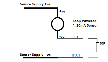
Connect the supplied cable as follows: Red to +ve, Blue to -ve
The Input Impedance of the 0 to 10V and 0 to 5V Voltage Input Sensor Transmitters is a nominal 10k, that of the 0 to 1V Voltage Input Sensor-Transmitter is 100k.
They can withstand a permanent over voltage of twice nominal and short term polarity reversal.
For 0 to 20mA Input Sensor-Transmitter, an internal load resistance of 50R and will normally be connected as shown in Figure 59 below.
The user must ensure that no more than 2V is applied across the Red and Blue Notion Pro connections under any circumstances. The 50R resistance shown is internal to the device; the user does NOT need to add this.
Figure 59
4-20mA Loop Powered Sensor Connection
Gain and Offset
With a Gain of 1.0 and Offset of 0 (default), the software will read V or mA directly.
To read in other engineering units set the Offset to be the voltage/current at which the device reads 0 and the Gain/Units as required.
Voltage Input Sensor-Transmitter
Example 1: A 0 to 1V Sensor-Transmitter corresponds to +/-100Bar:
Offset = 0.500
Gain = 100/0.5 = 200
Units = ’BAR’
4-20mA Input Sensor-Transmitter
For 4 to 20mA Input Sensor-Transmitter: Gain = Sensor Range/16, Offset = 4 (Minimum Sensor Reading/Gain).
Example 2: A 4 to 20mA Sensor-Transmitter corresponds to 0 to 100Bar:
Offset = 4.00
Gain = 100/16 = 6.25
Units = ’BAR’
Example 3: A 4 to 20mA Sensor-Transmitter corresponds to 90 to 100Bar:
Gain = (100 – 90)/16 = 0.625
Offset = 4 (90/0.625) = -140
Units = ’BAR’
| Caution: | Applying signals levels over the limits stated above may damage the unit and will invalidate the warranty |